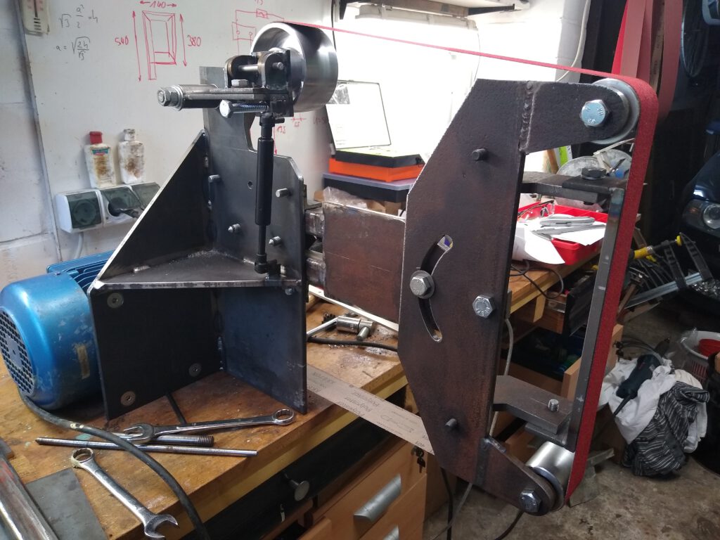
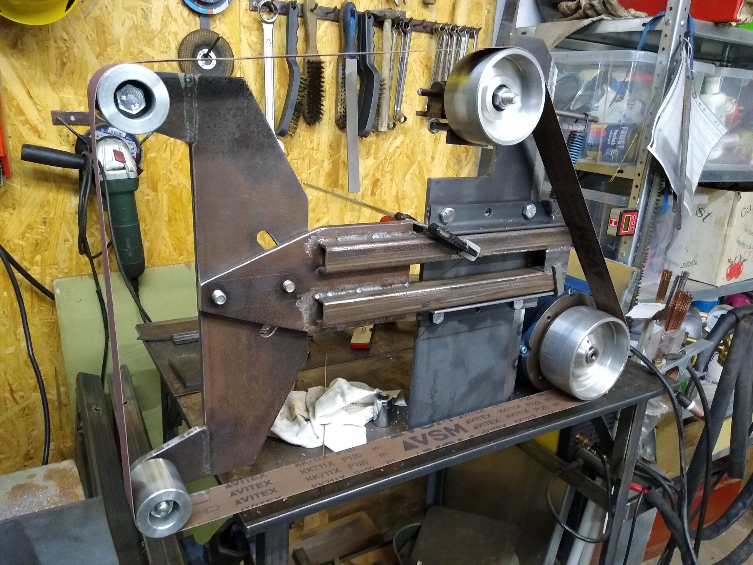
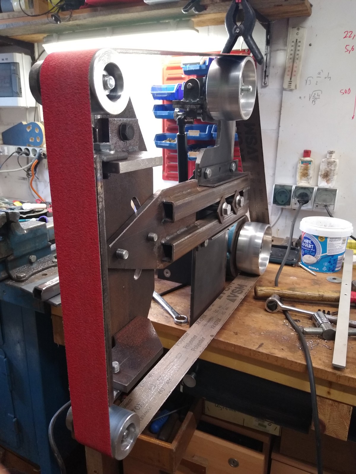
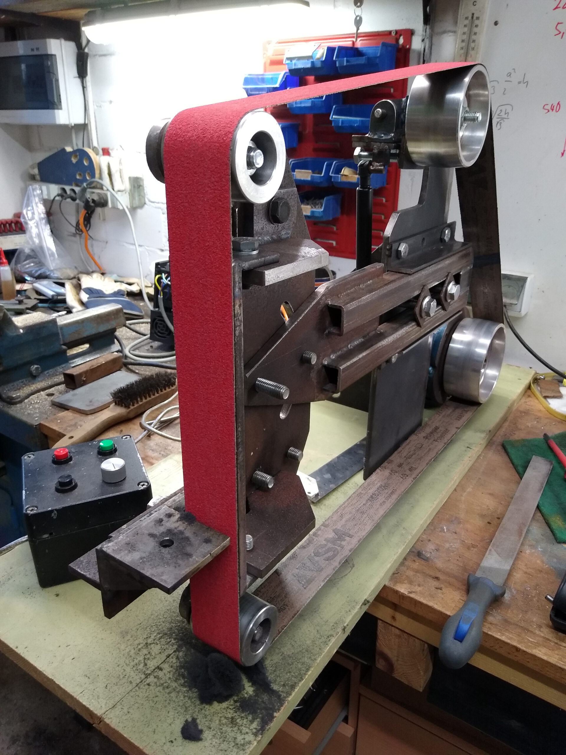
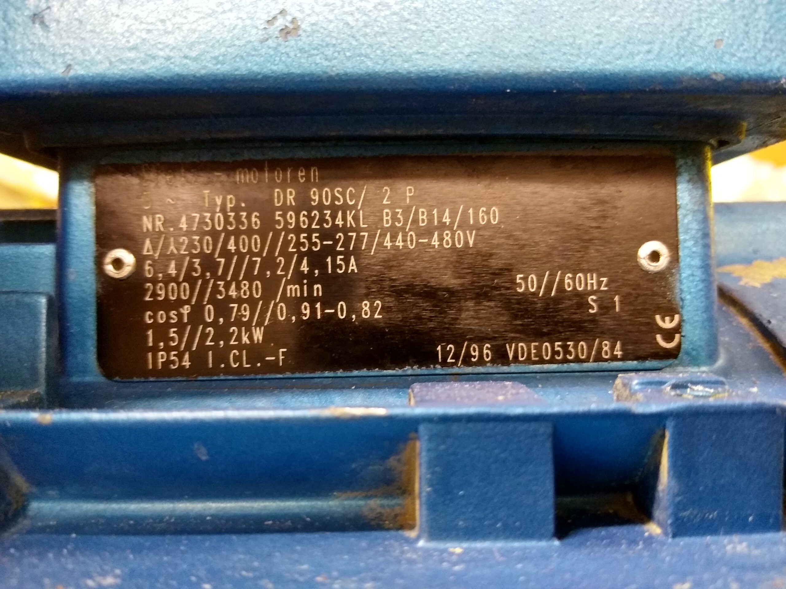
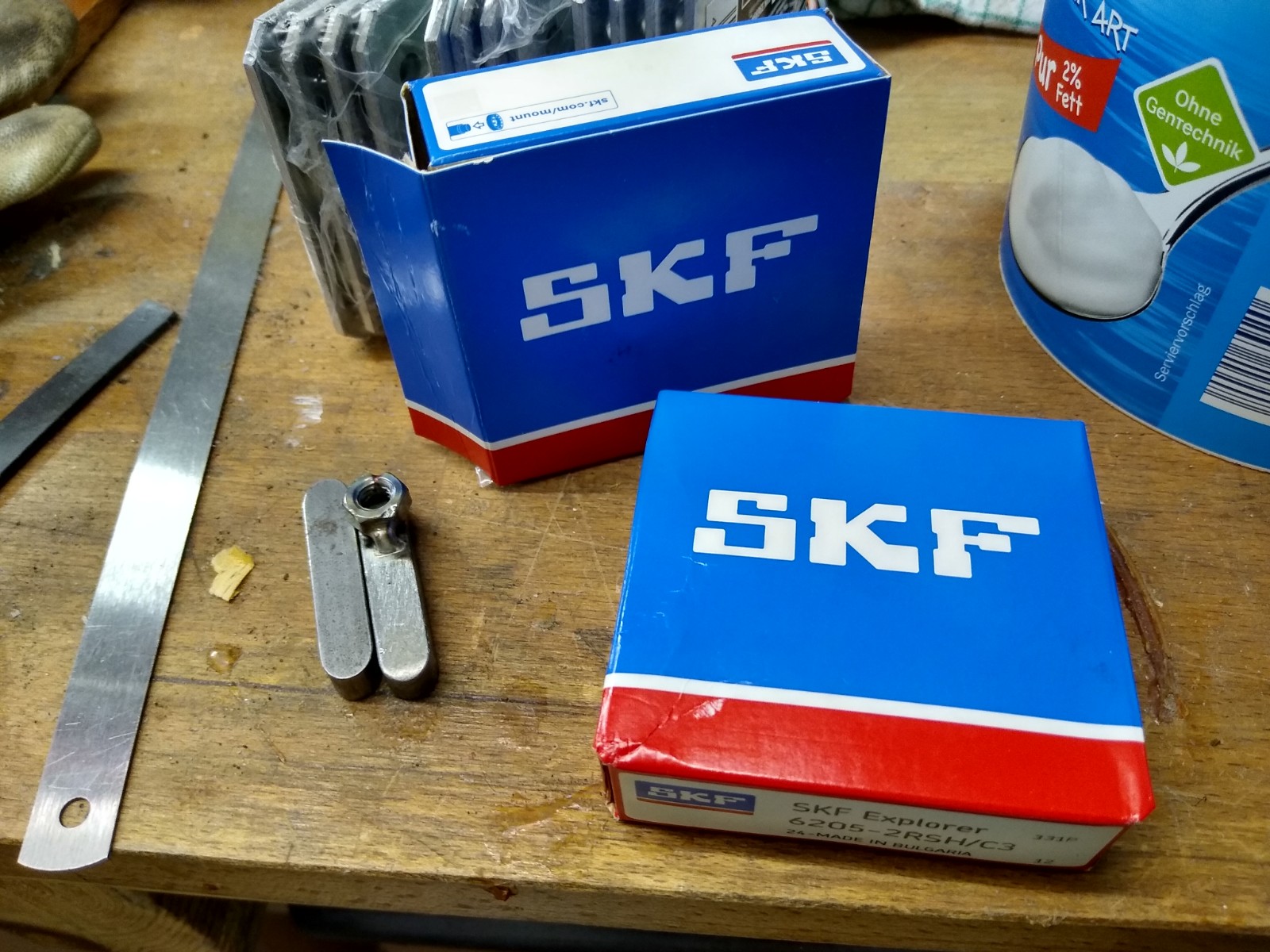
This article will give a rough overview of how I built a 2×72 belt grinder (more specifically 50×2000 mm). I tried to keep this project as cheap as I could using a combination of old and new parts. It probably won’t make sense to copy my grinder exactly and there are certainly more elaborate designs out there. It all comes down to how much you are willing to invest. The rollers are from ebay by a Polish manufacturer. The motor is a used three phase 1,5 kW pump motor with S1 rating. It also came with shot bearings which I had to replace (see below).
Main structure
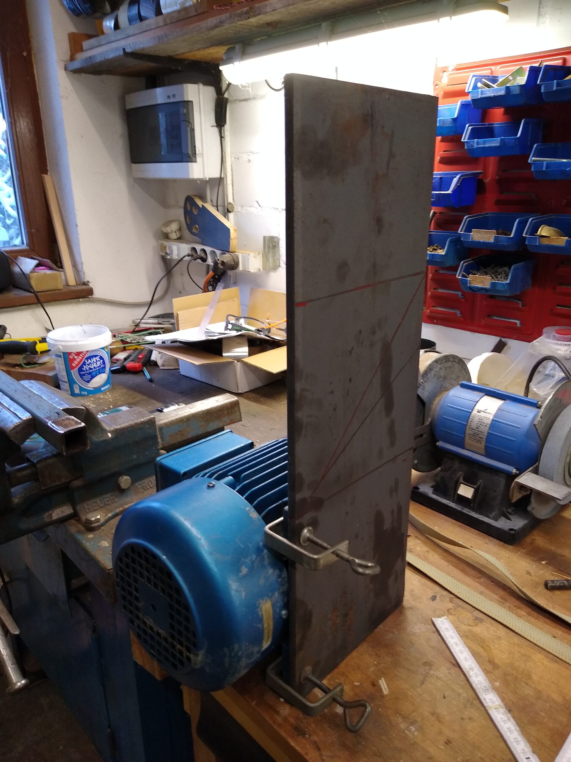
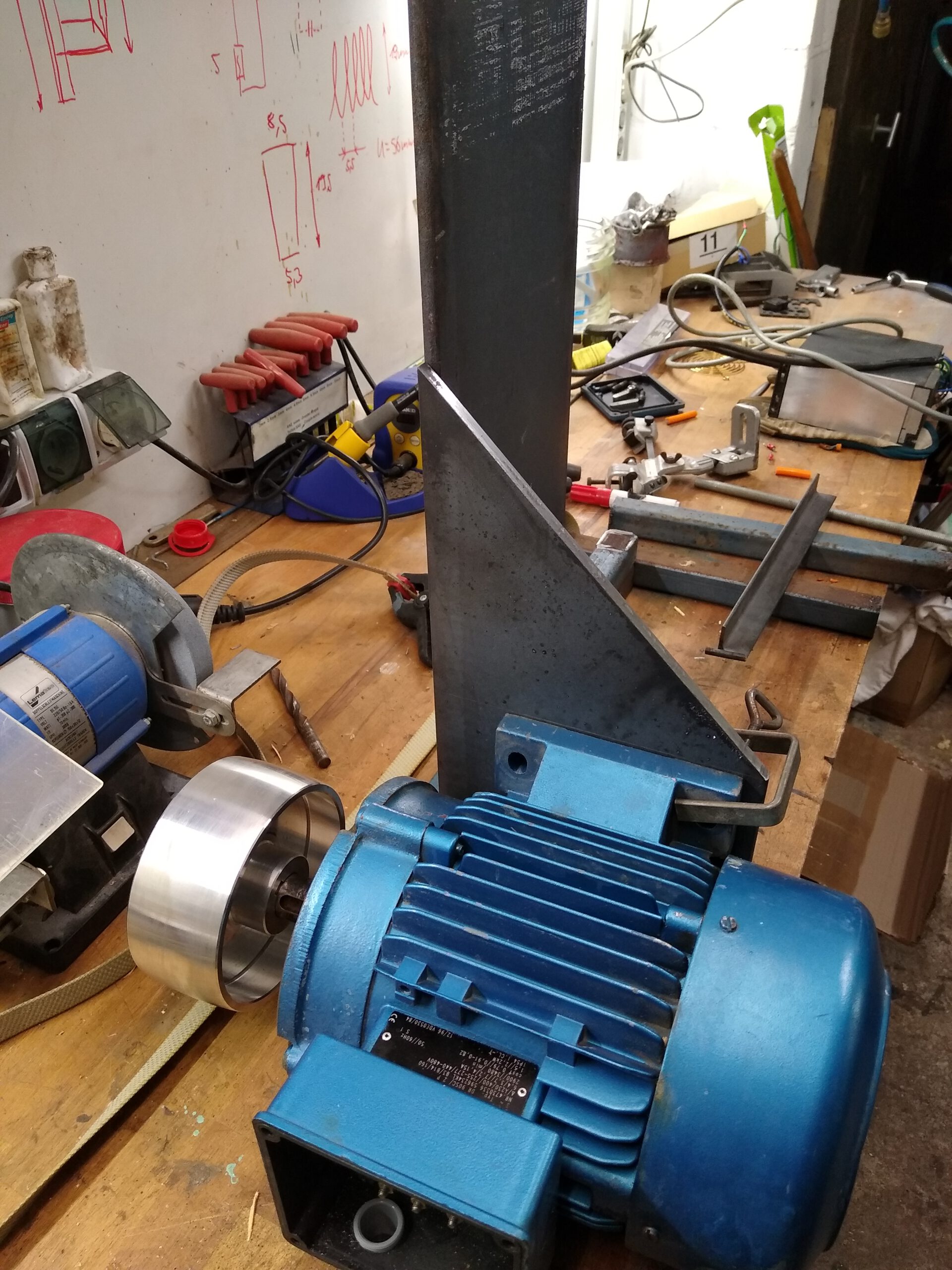
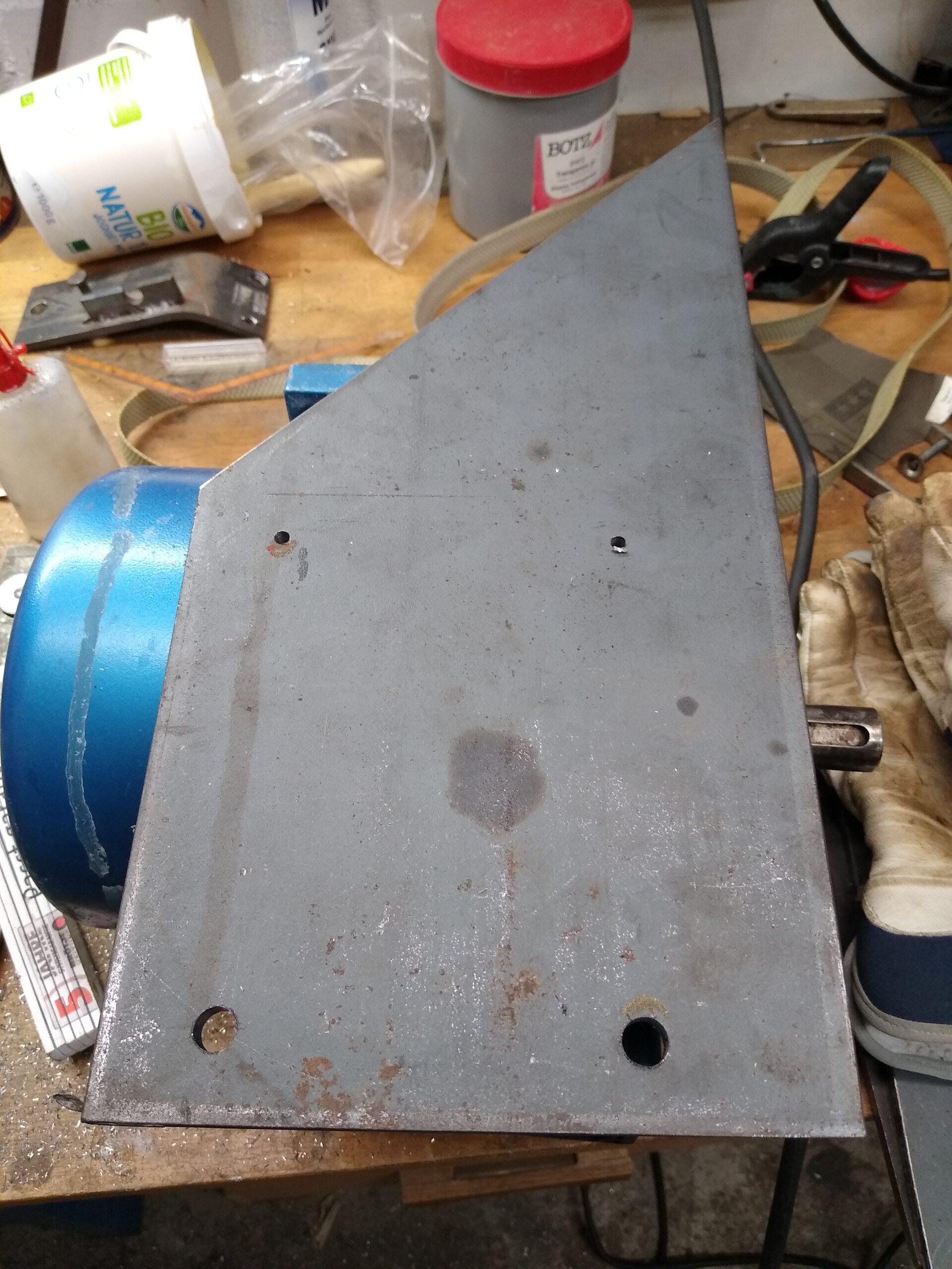
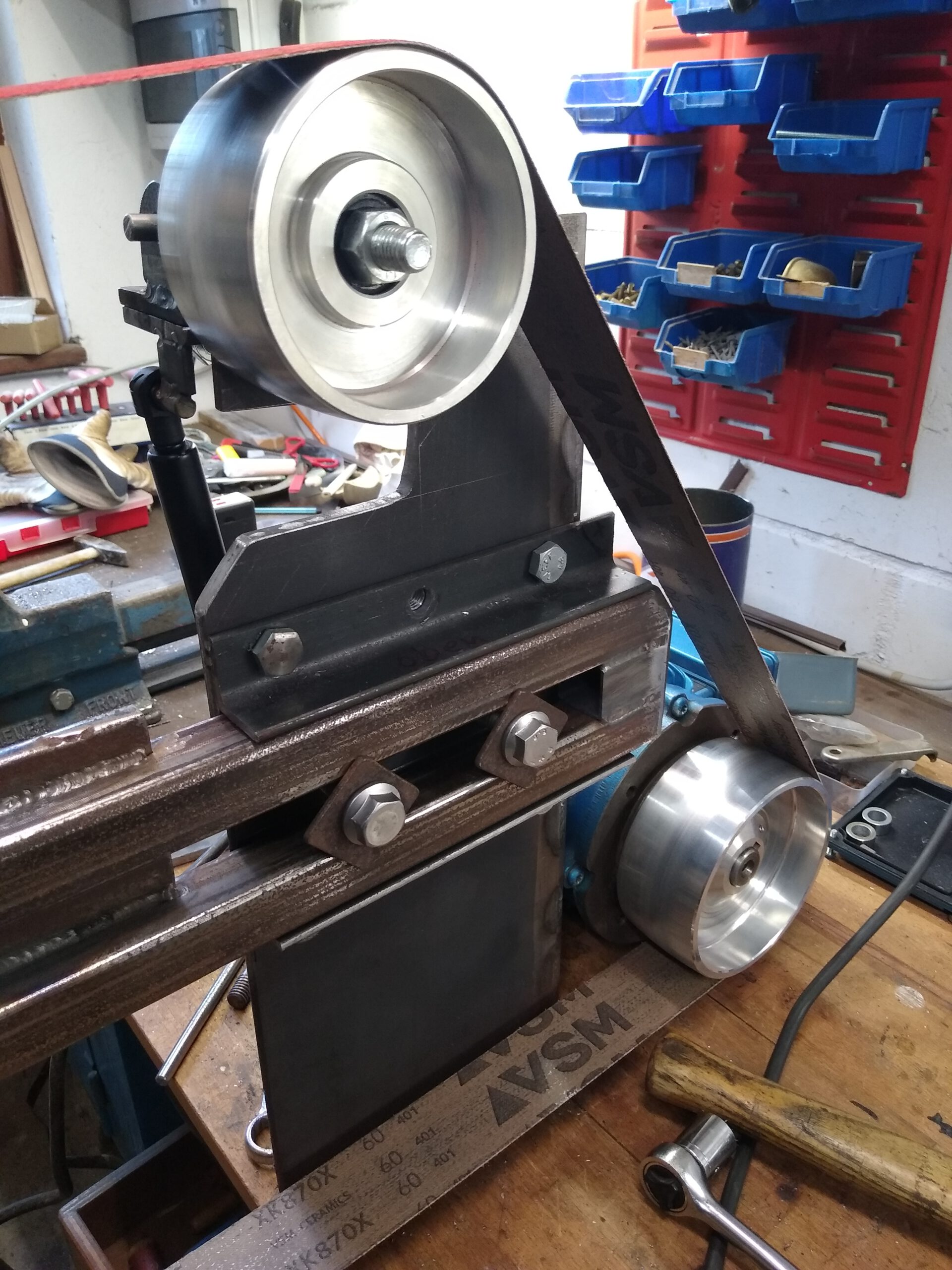
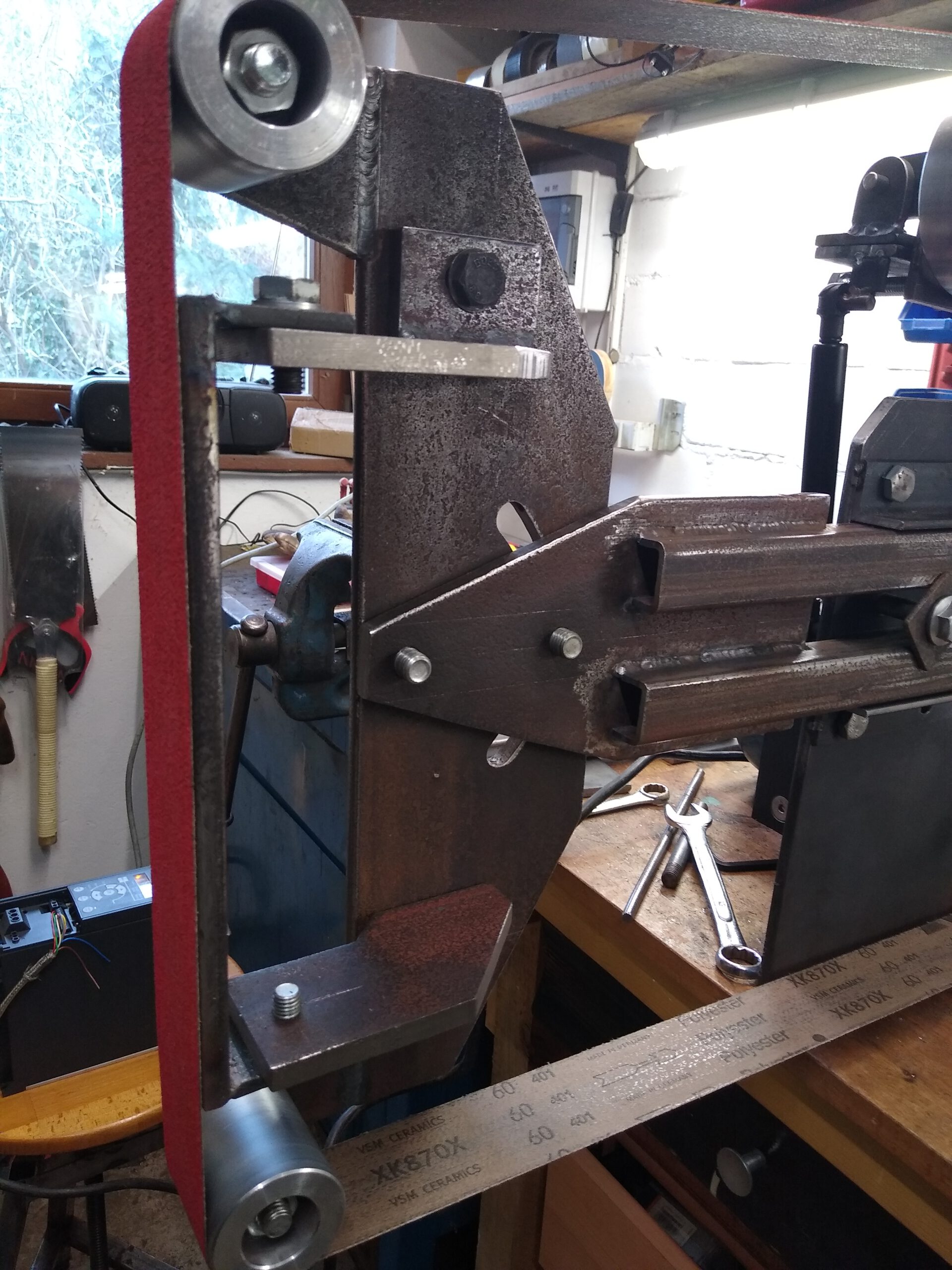
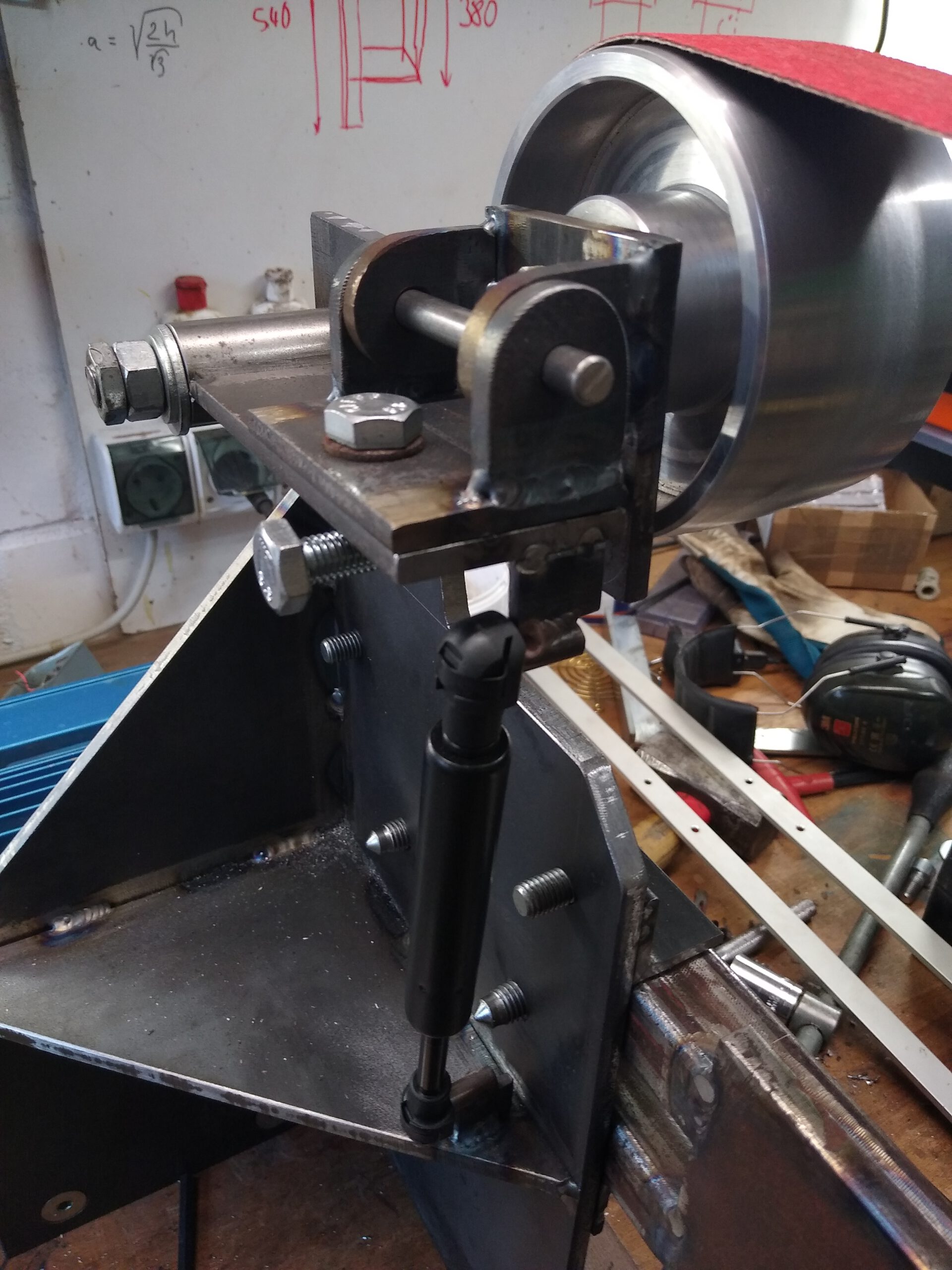
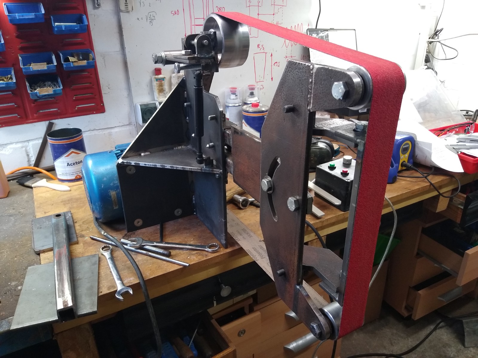
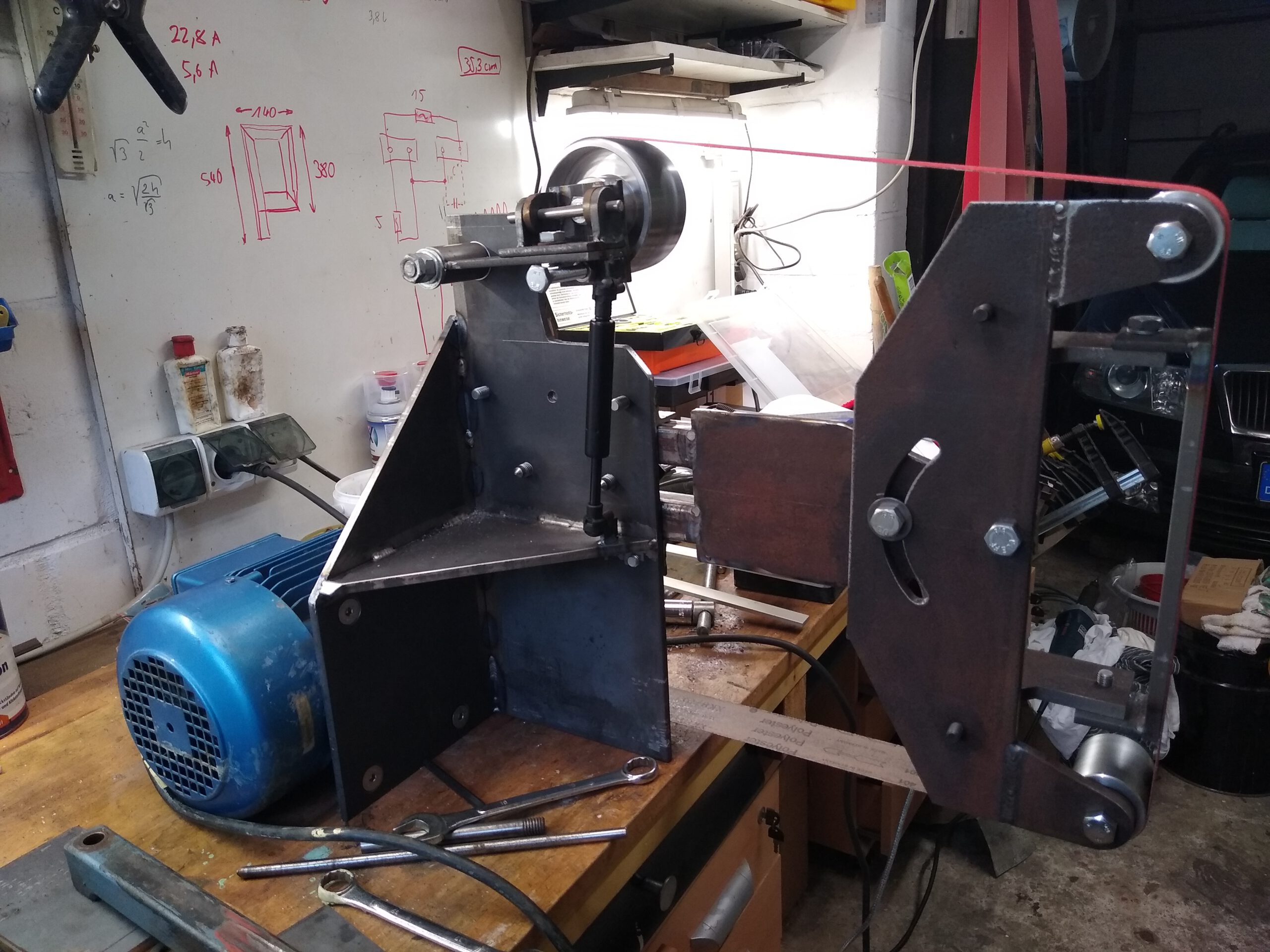
I started with two pieces of steel plate (around 8 mm thick) which are welded together at a 90° angle and are reinforced by a triangular piece of plate. The motor gets mounted to one plate while the other plate will accept the arm that carries the two small rollers and the platten. It will also hold the spring loaded guide roller on top.
Attachment
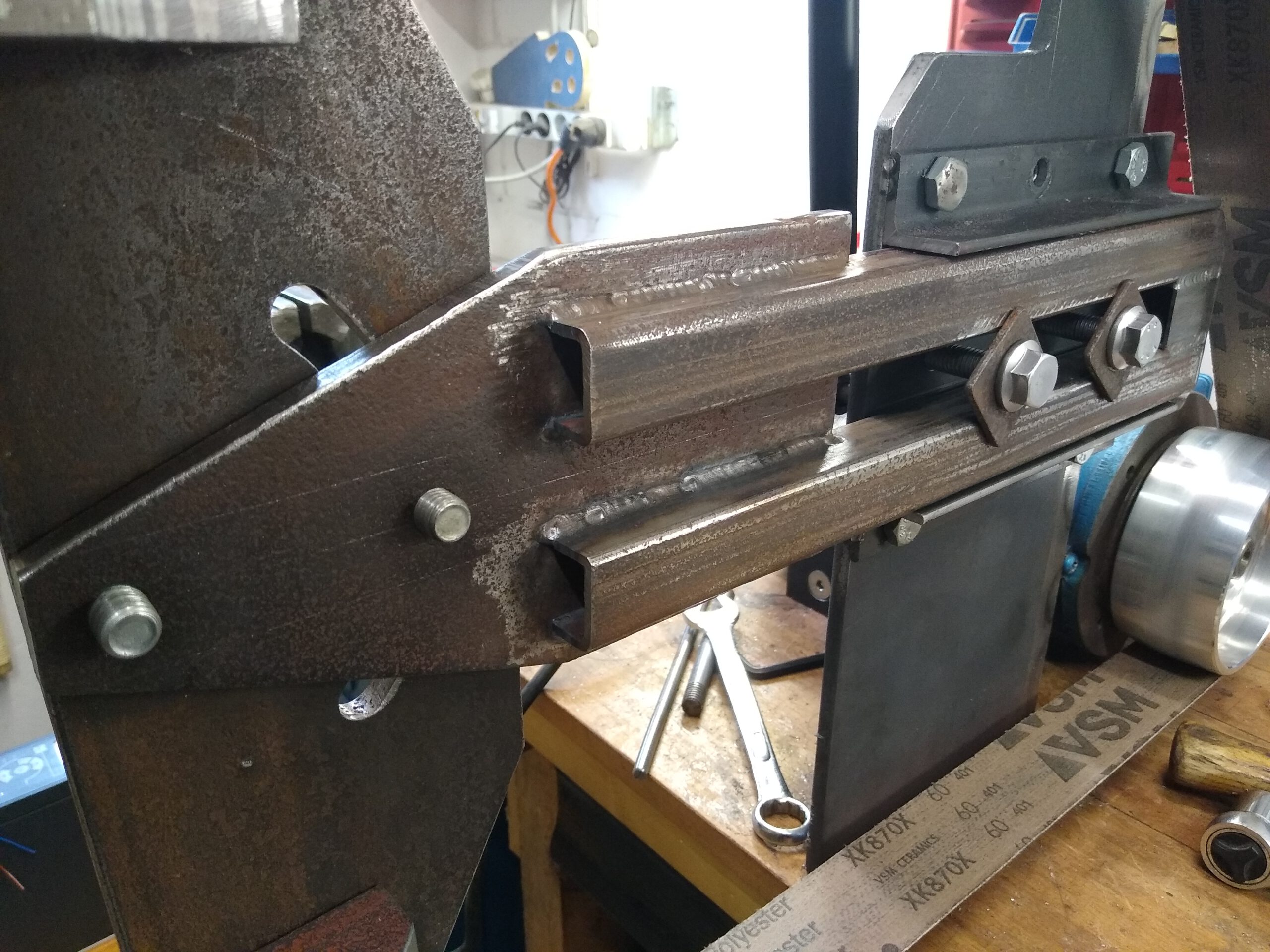
The arm holding the front rollers and platten is mostly made from scrap. I used to parallel pieces of square tubing to make a rail that gets clamped to the plate I mentioned earlier. This rail rides between two pieces of angle iron so it can be adjusted front to back. The plate for the adjustable roller and platten holder wasn’t big enough so I welded those noses to the plate for accepting the rollers.
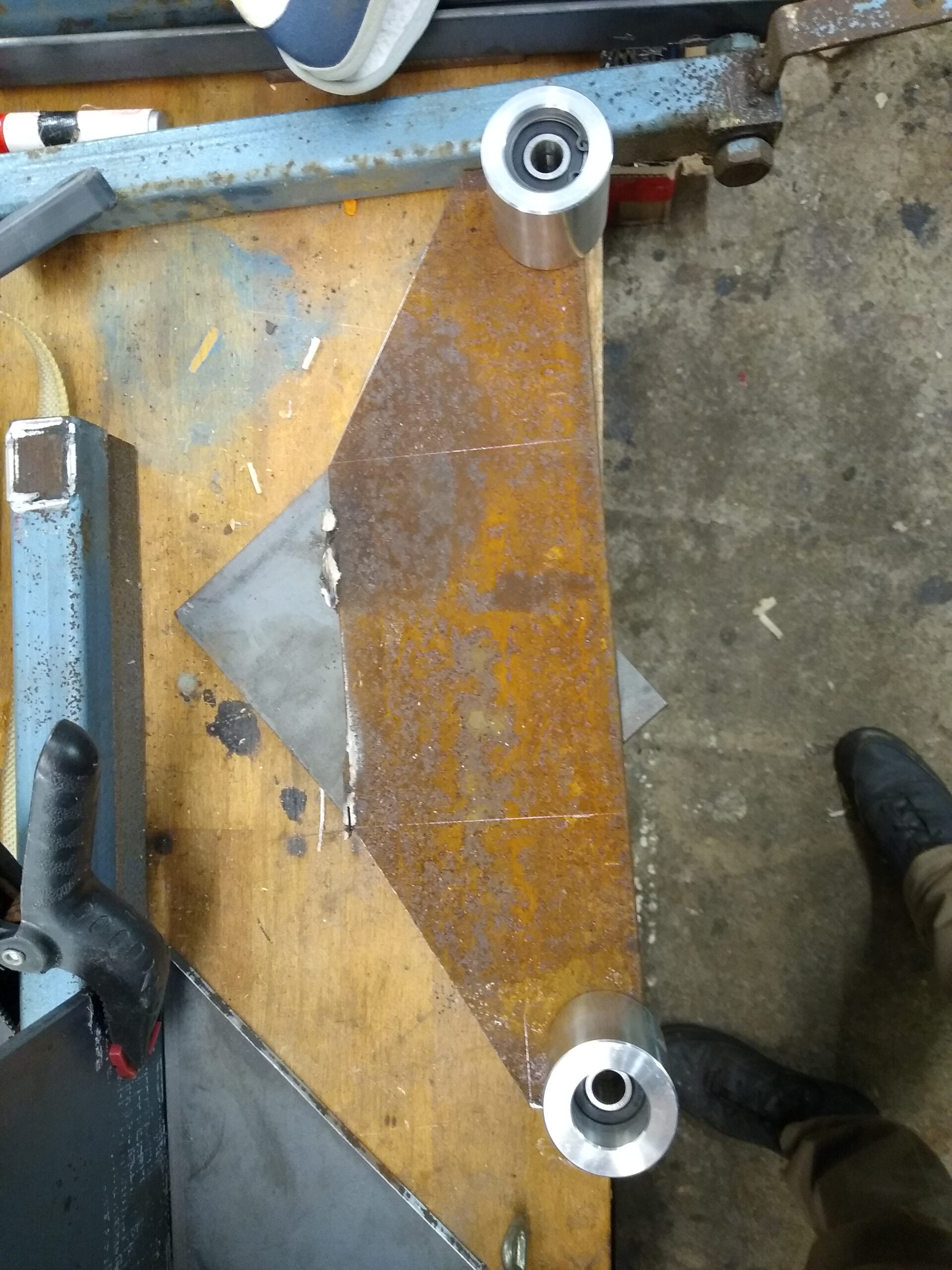
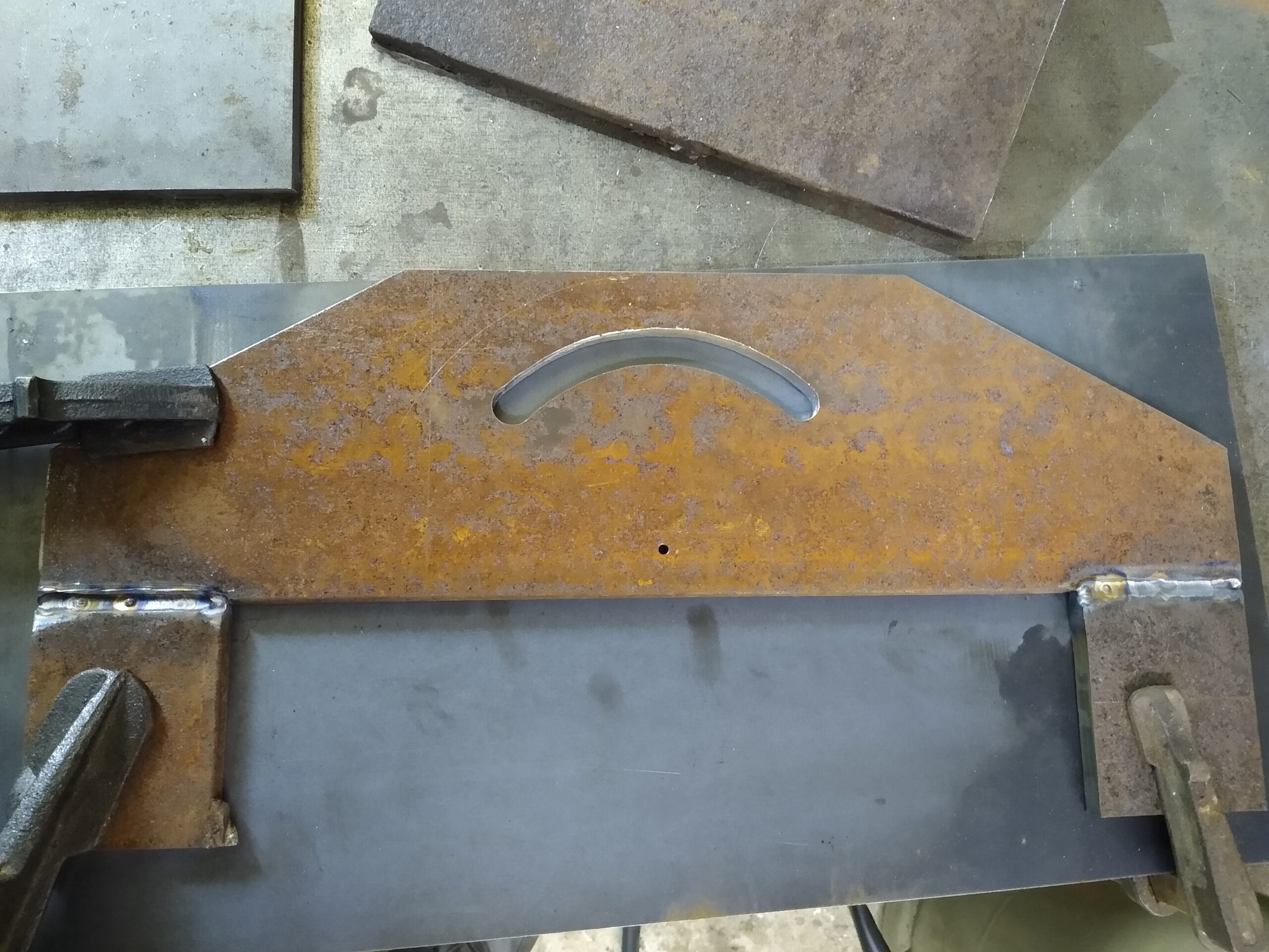
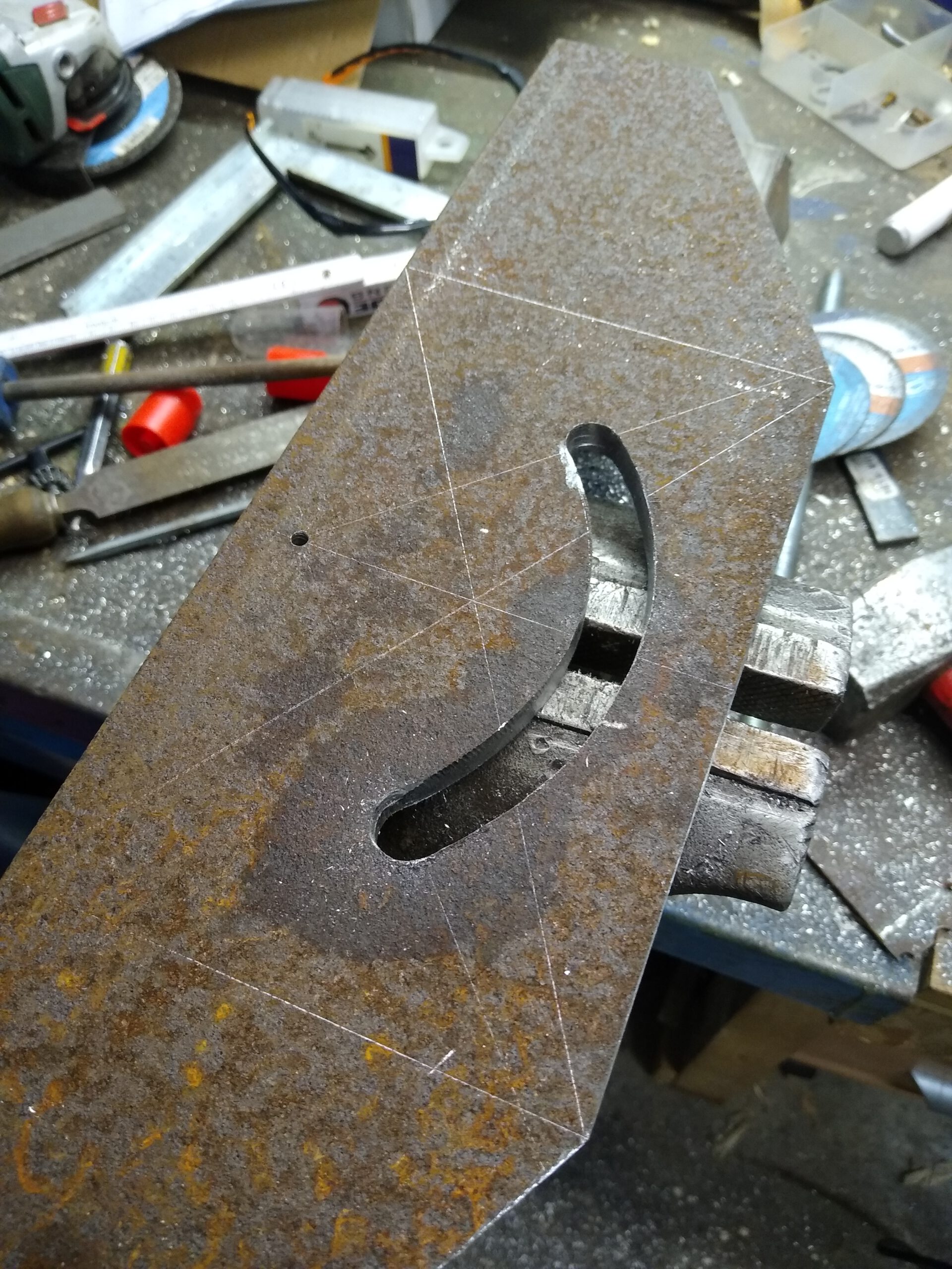
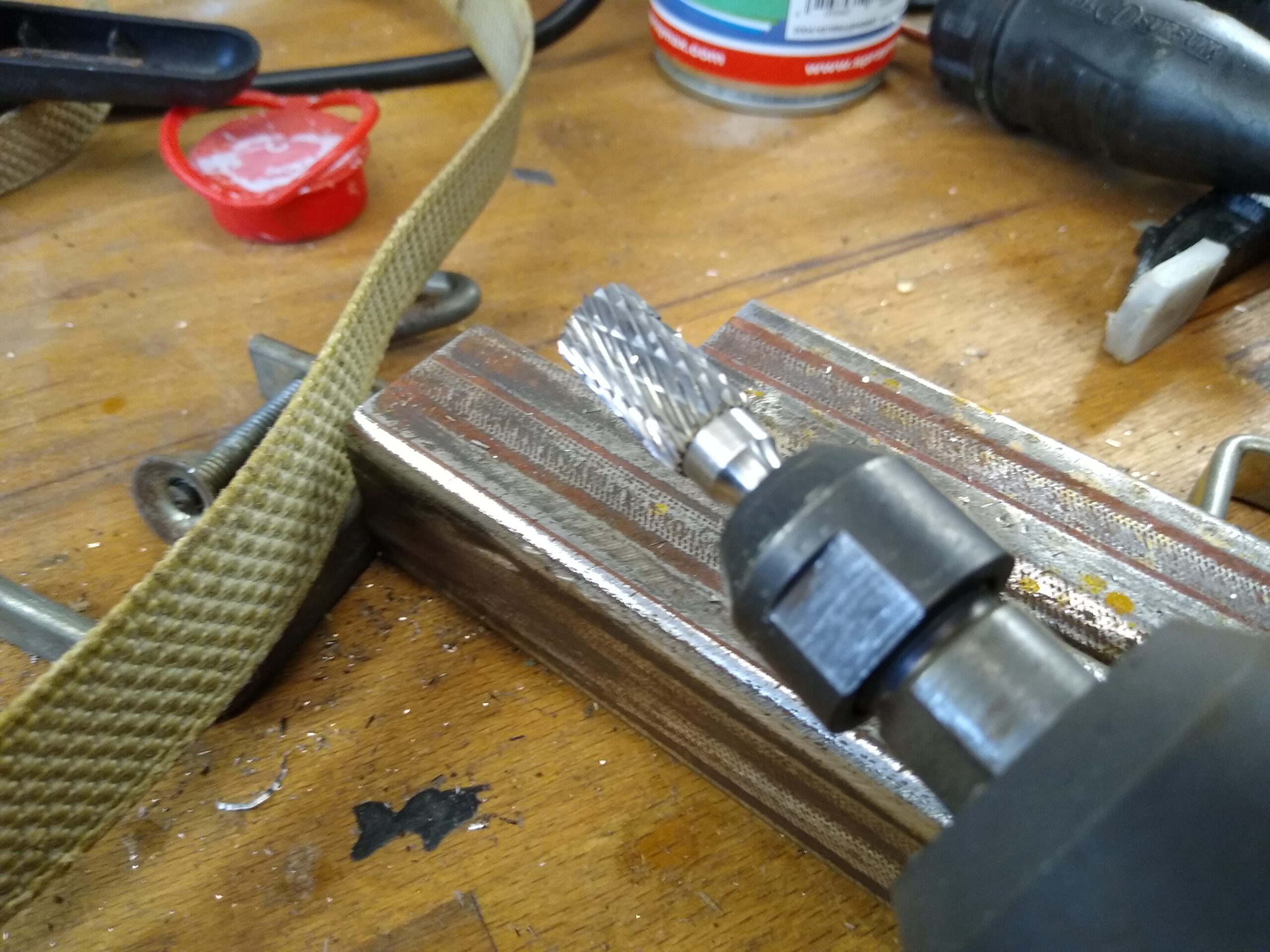
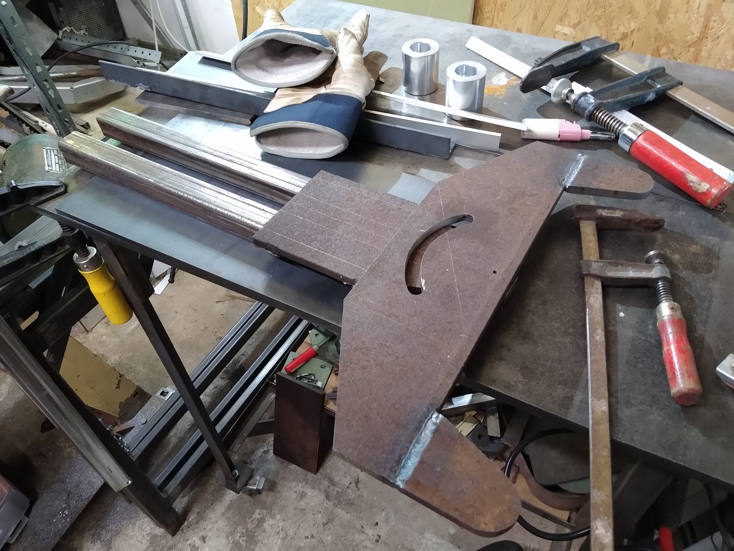

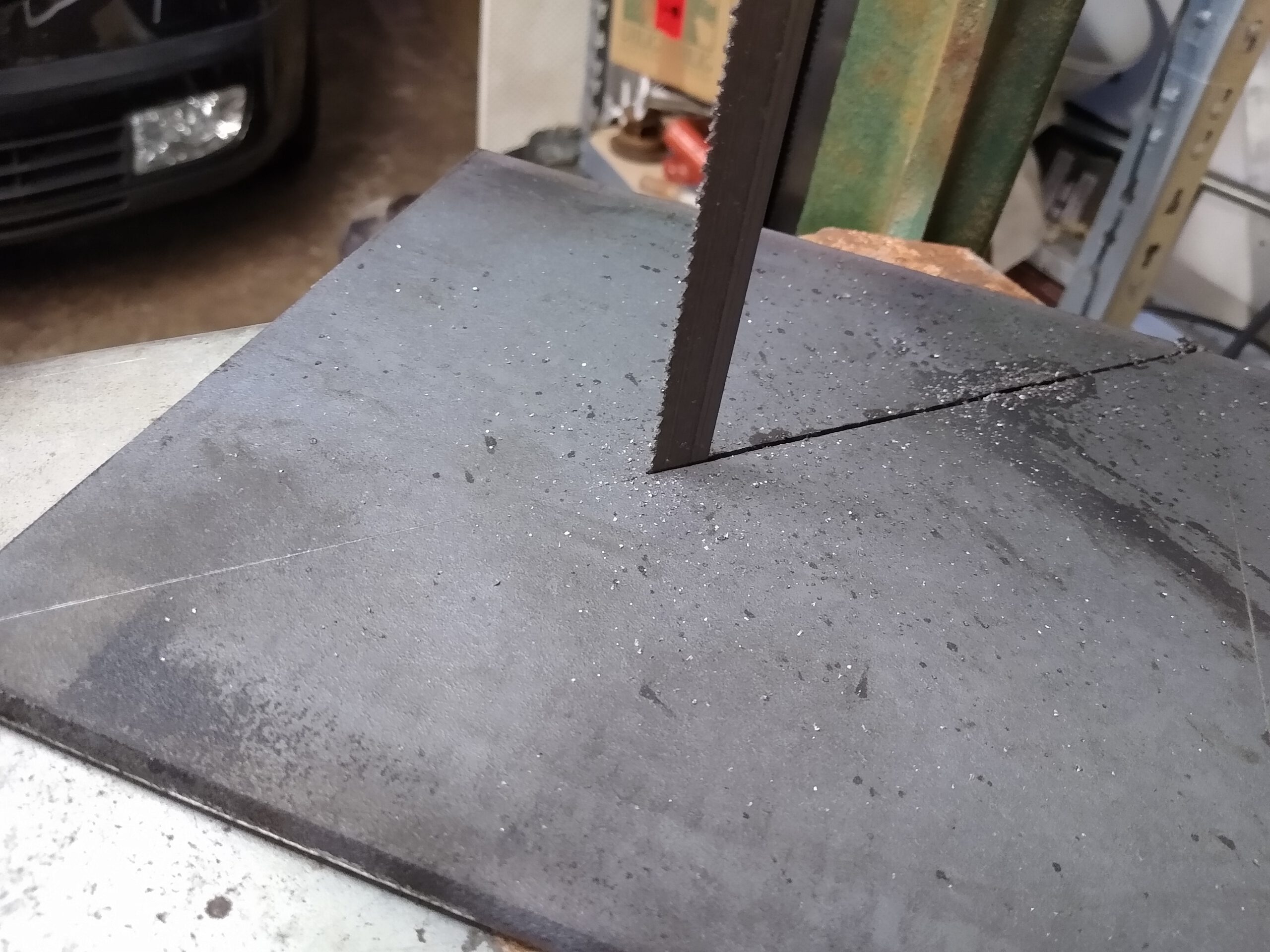
For the curved slot I marked the arch with a compass, drilled a series of holes and then used a carbide burr on a die grinder to smooth the slot.


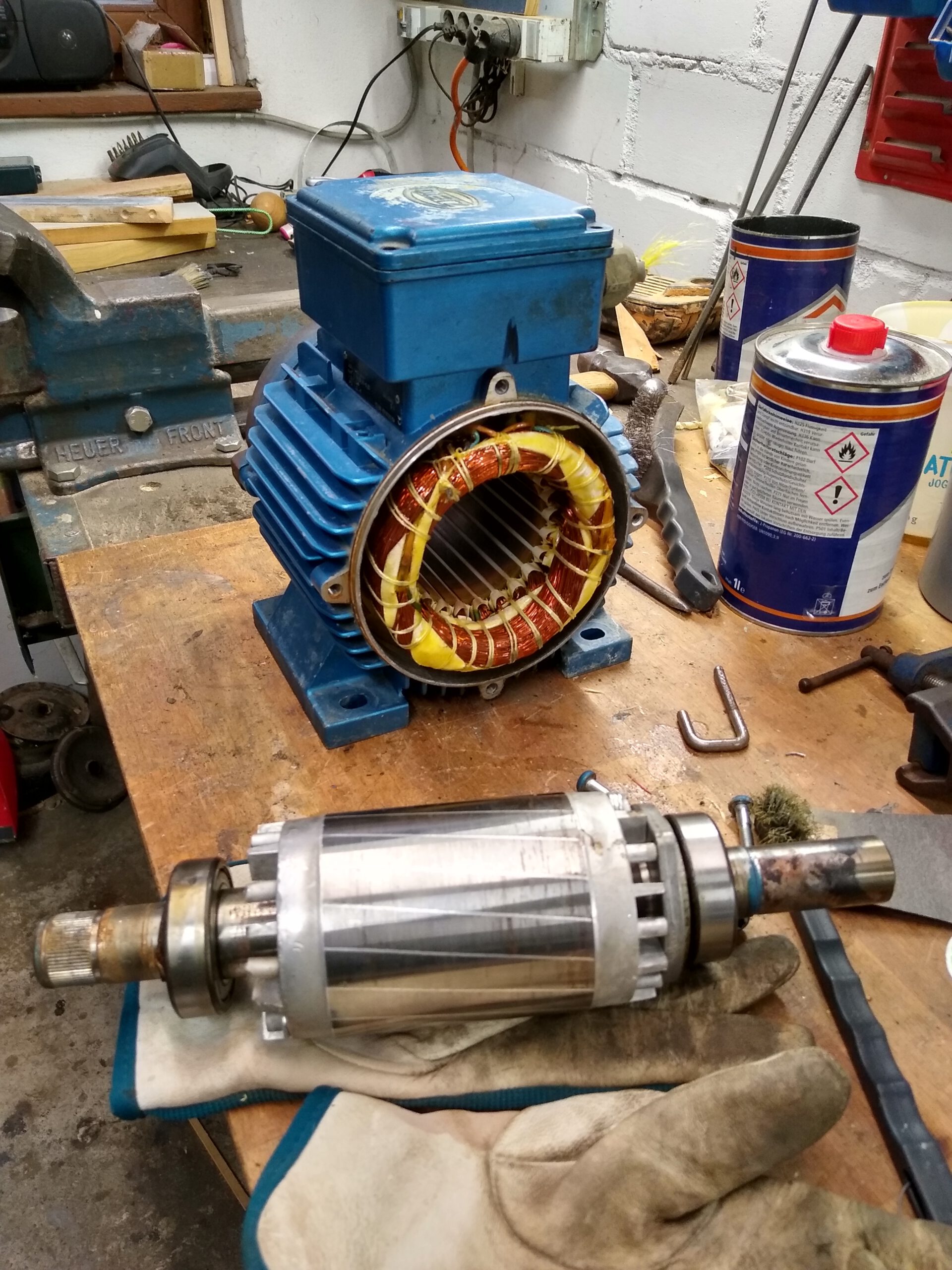
Motor
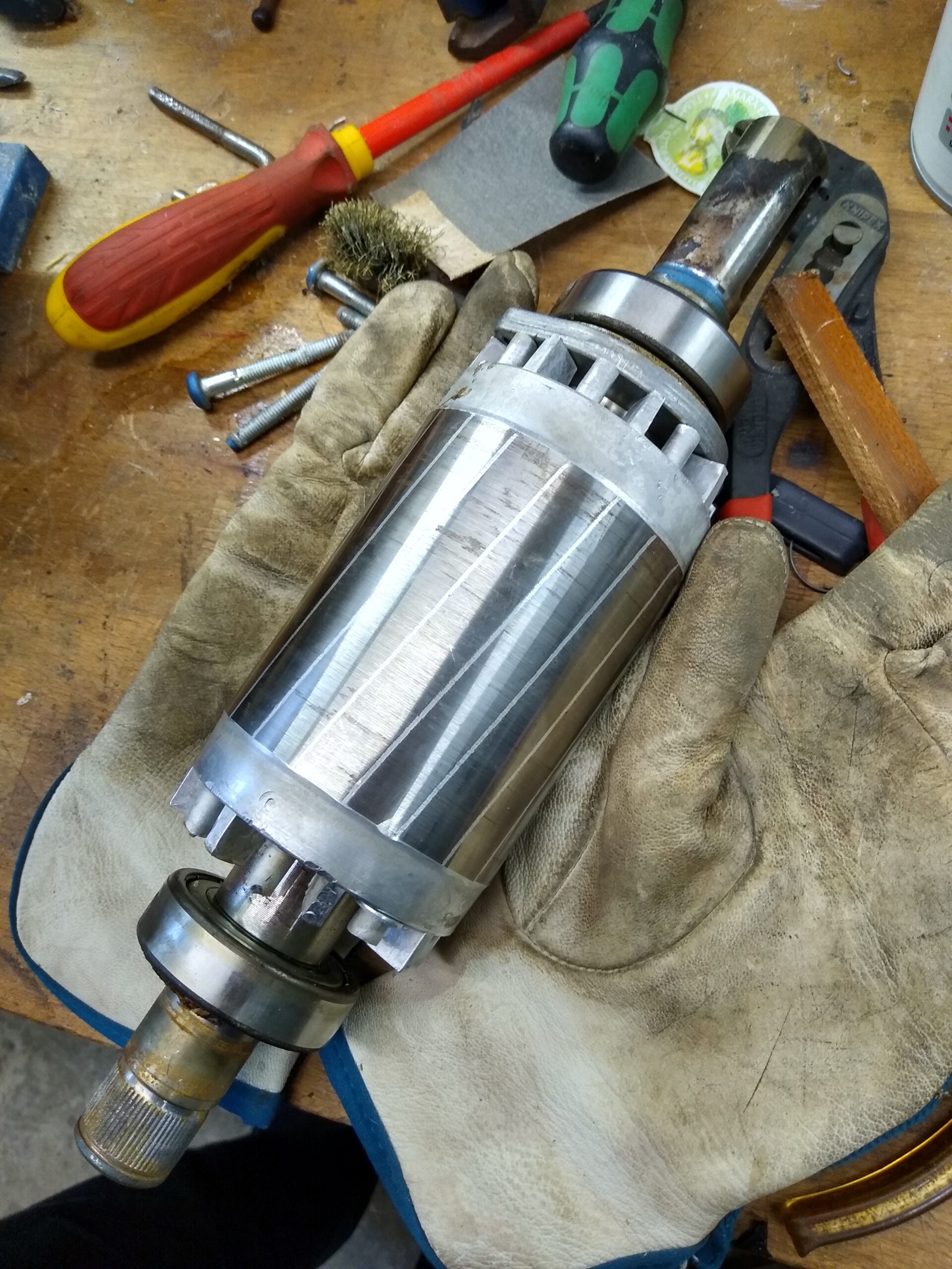
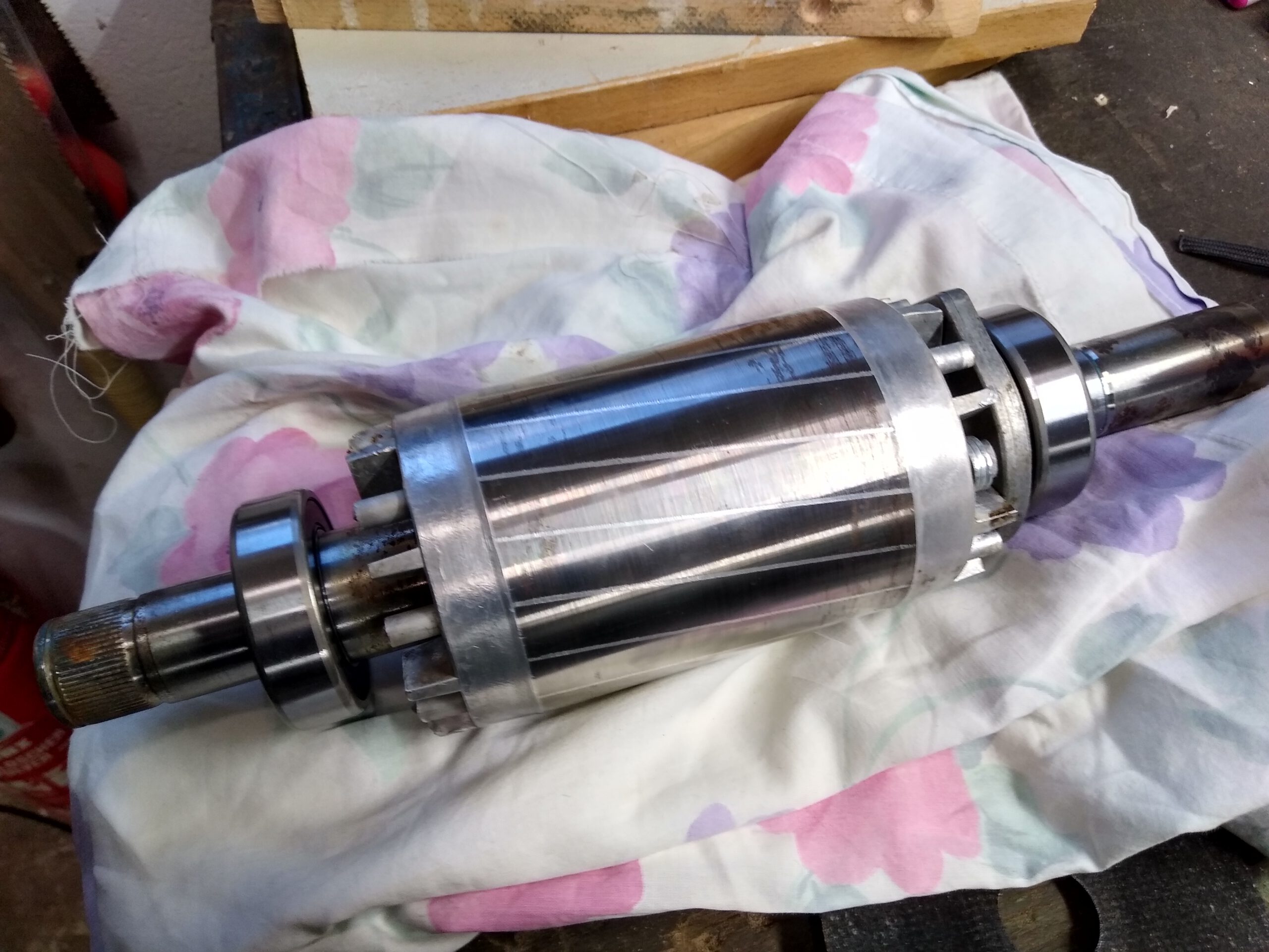
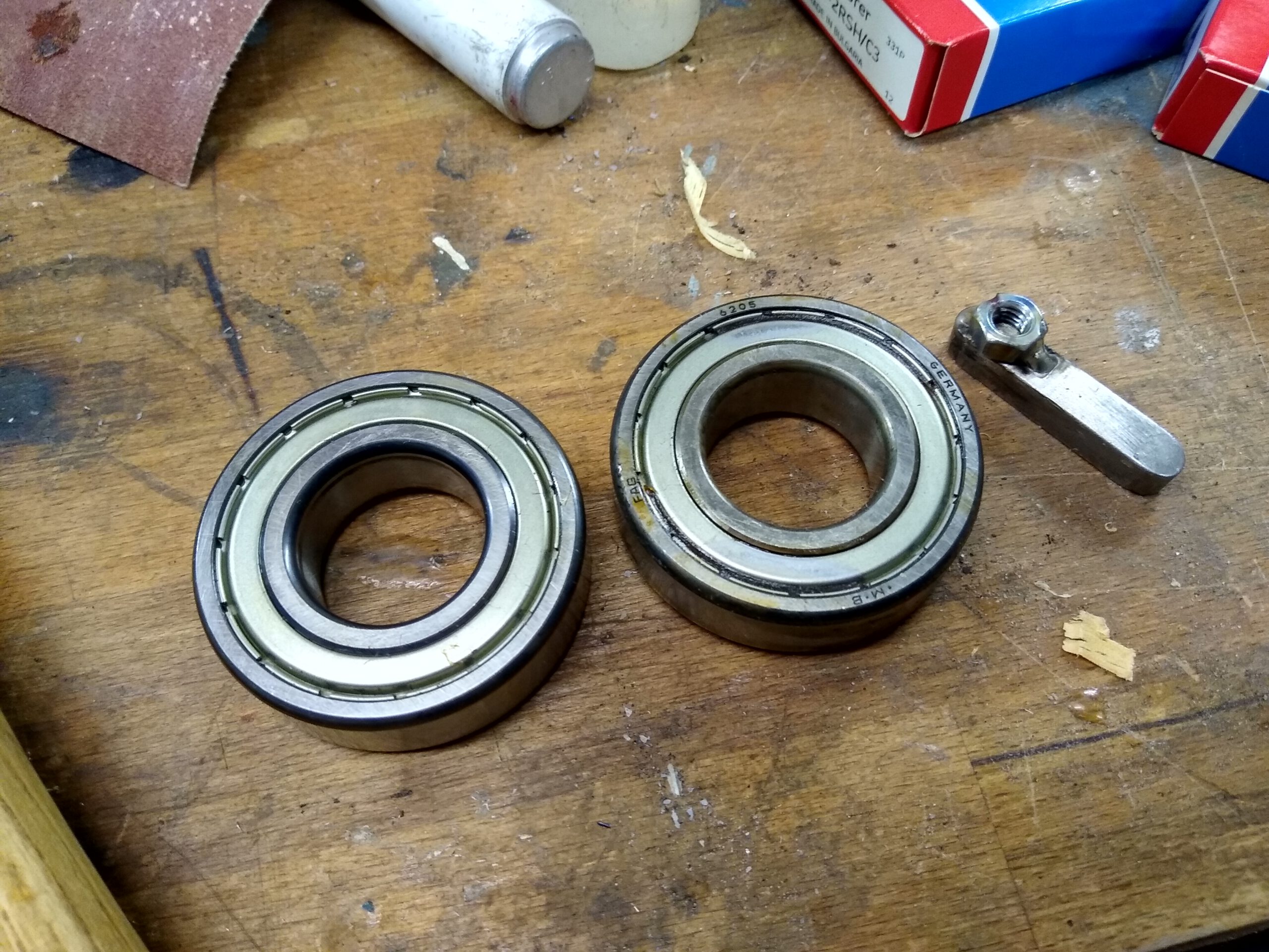
The motor is over 20 years old and I had to replace the bearings. Otherwise it still looked pretty good.
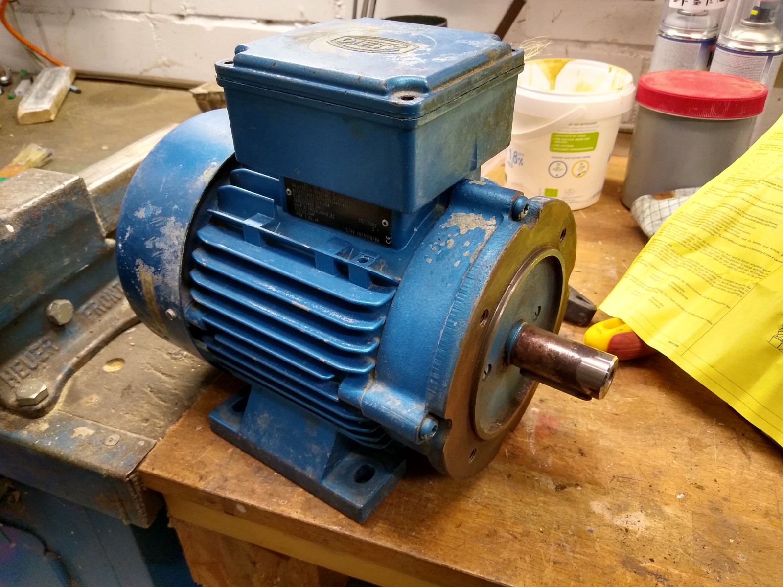
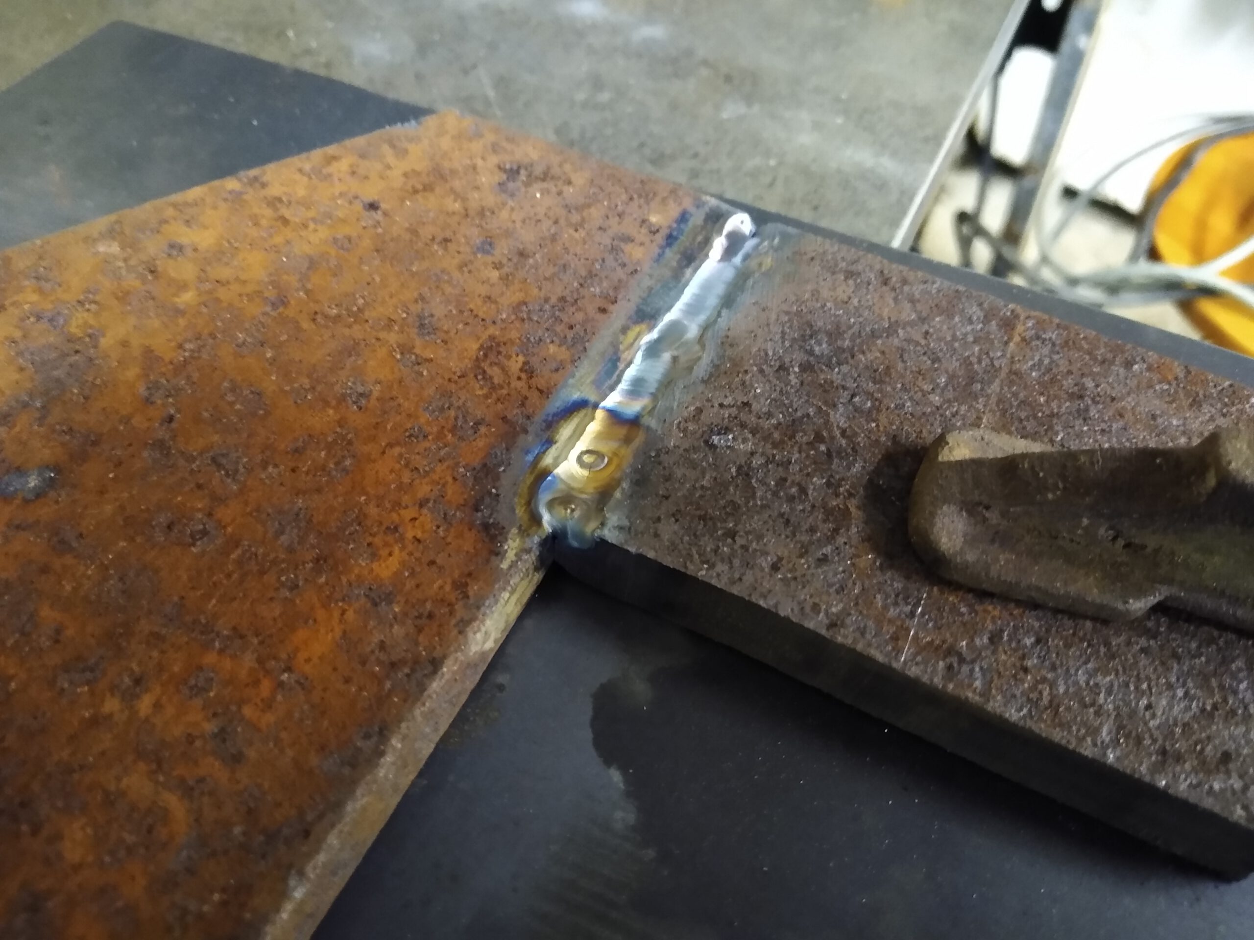
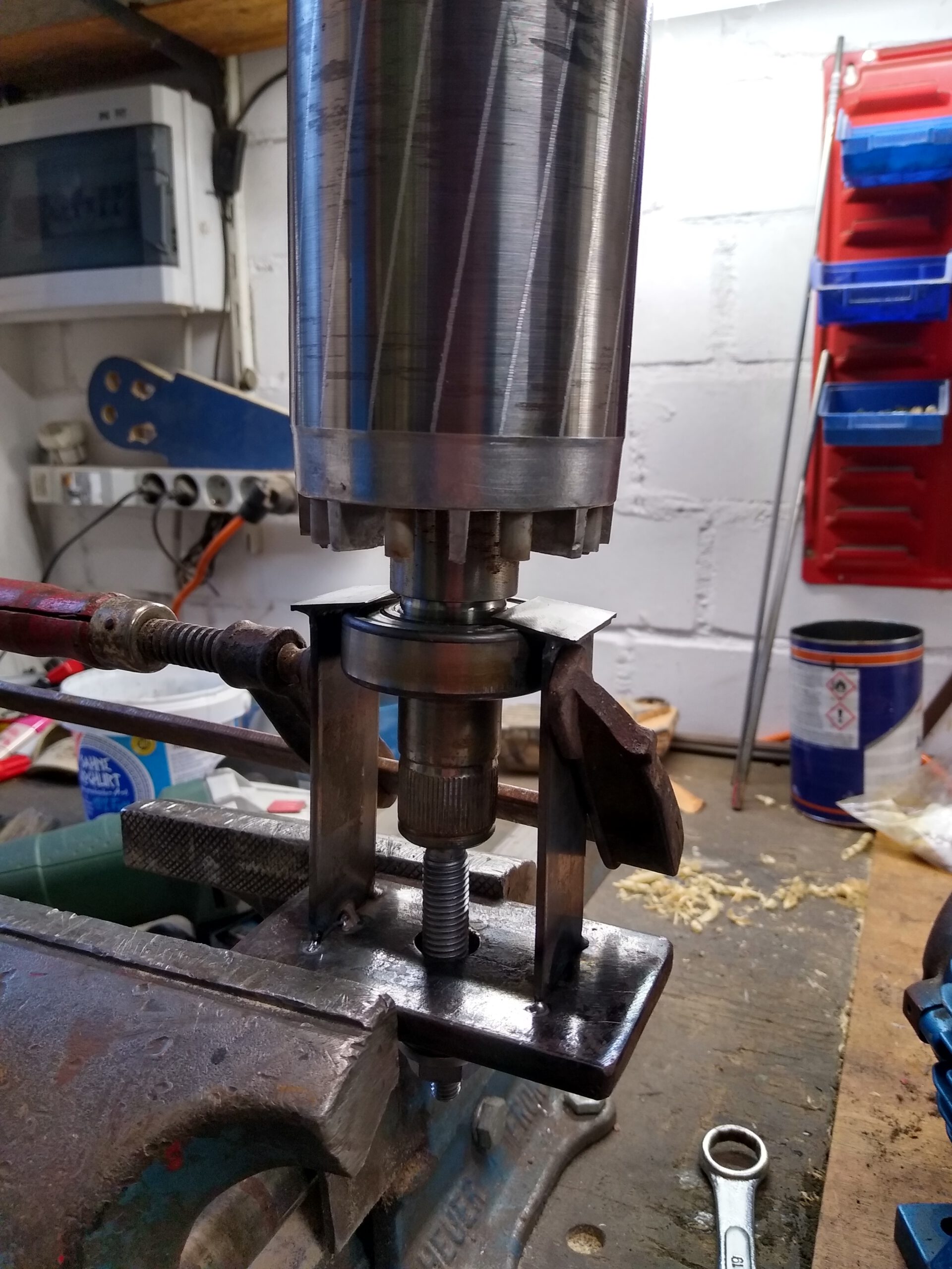
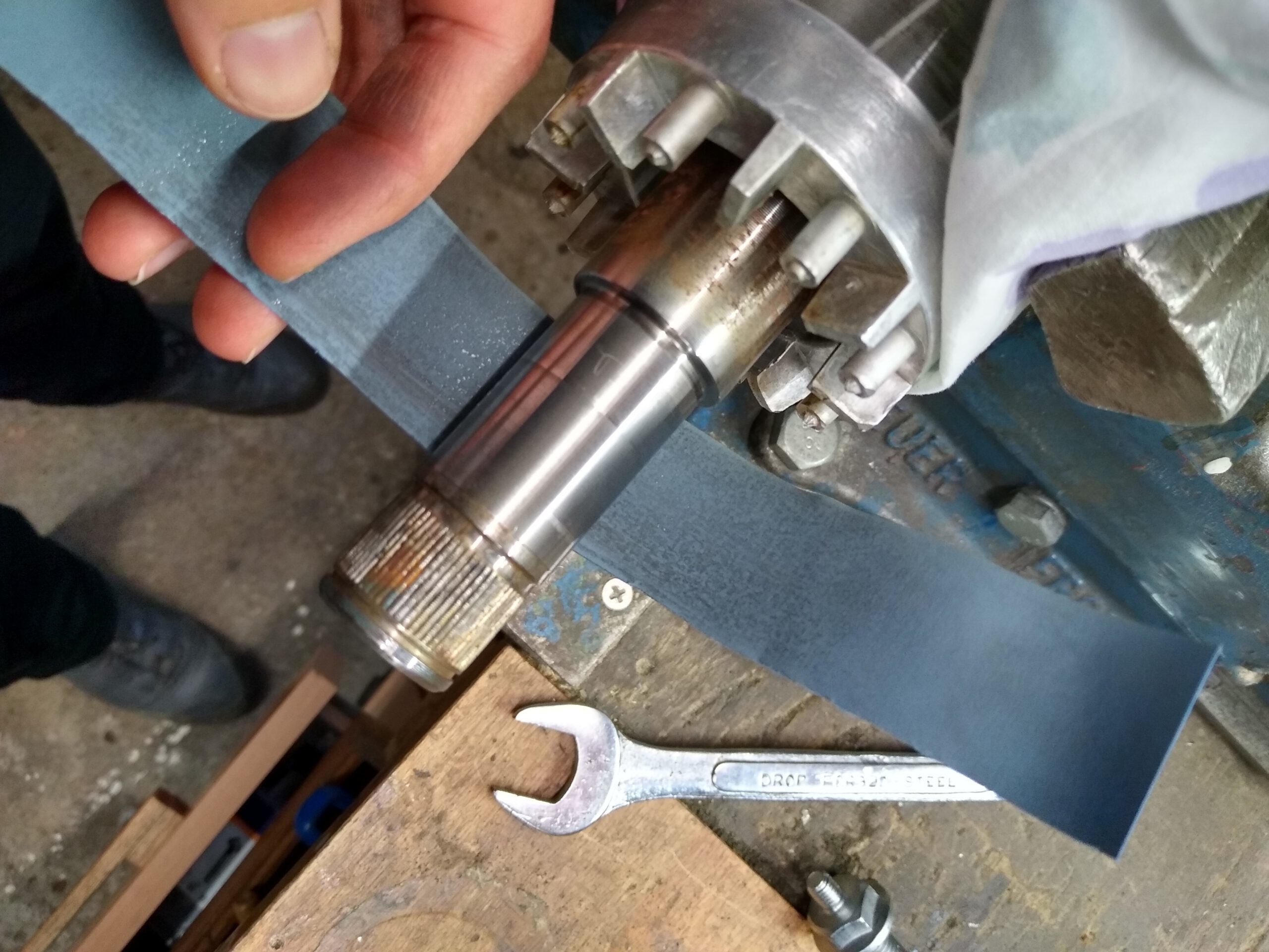
To get the old bearings off the shaft I had to make a bearing puller because I don’t own one and if I had one it probably wouldn’t be able to reach in the small area behind the bearing. Turns out the old bearings are FAG and made in Germany. Also I had a tough time getting the key out. I TIG welded a small nut to the key to pull it out.
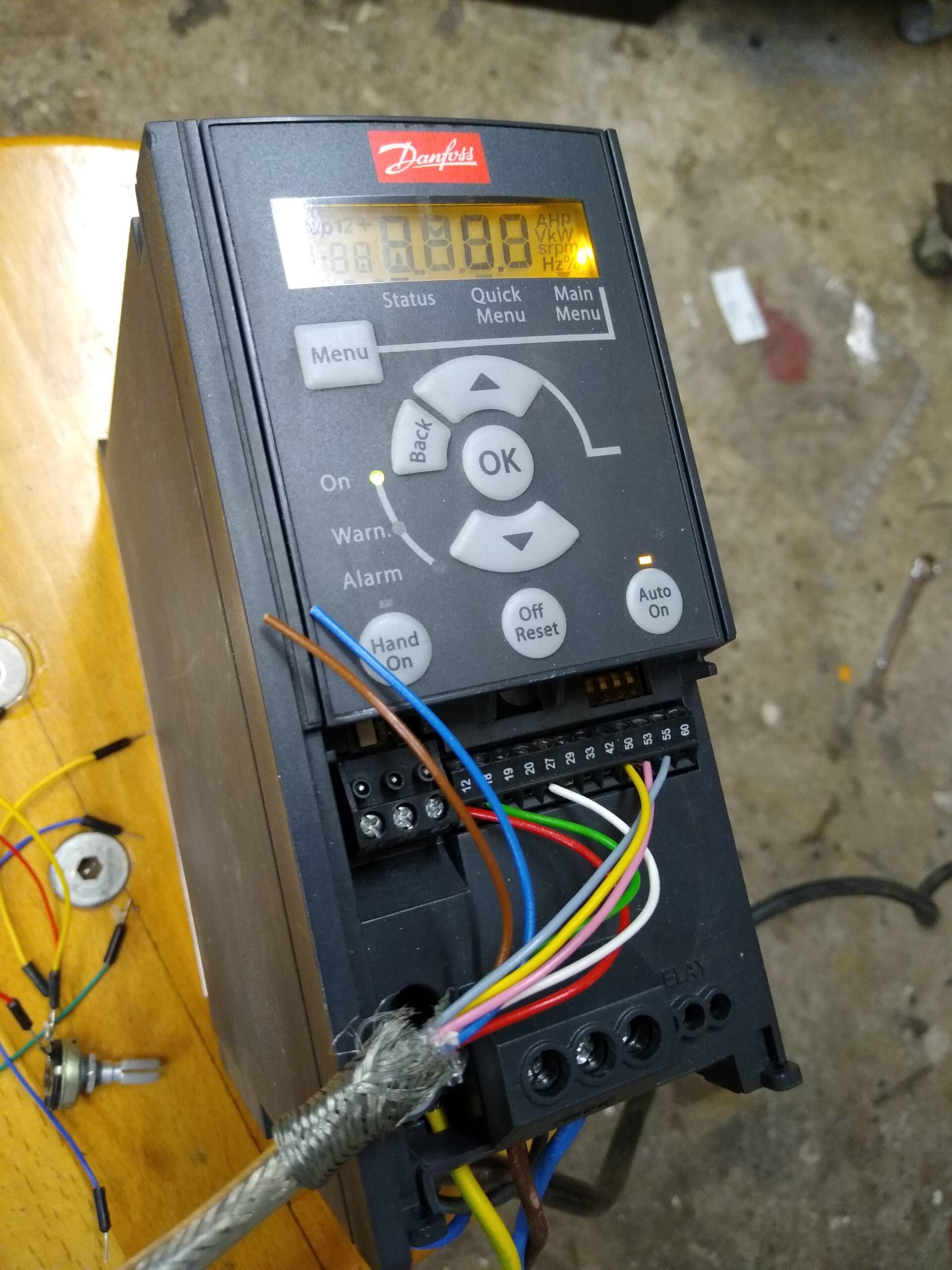
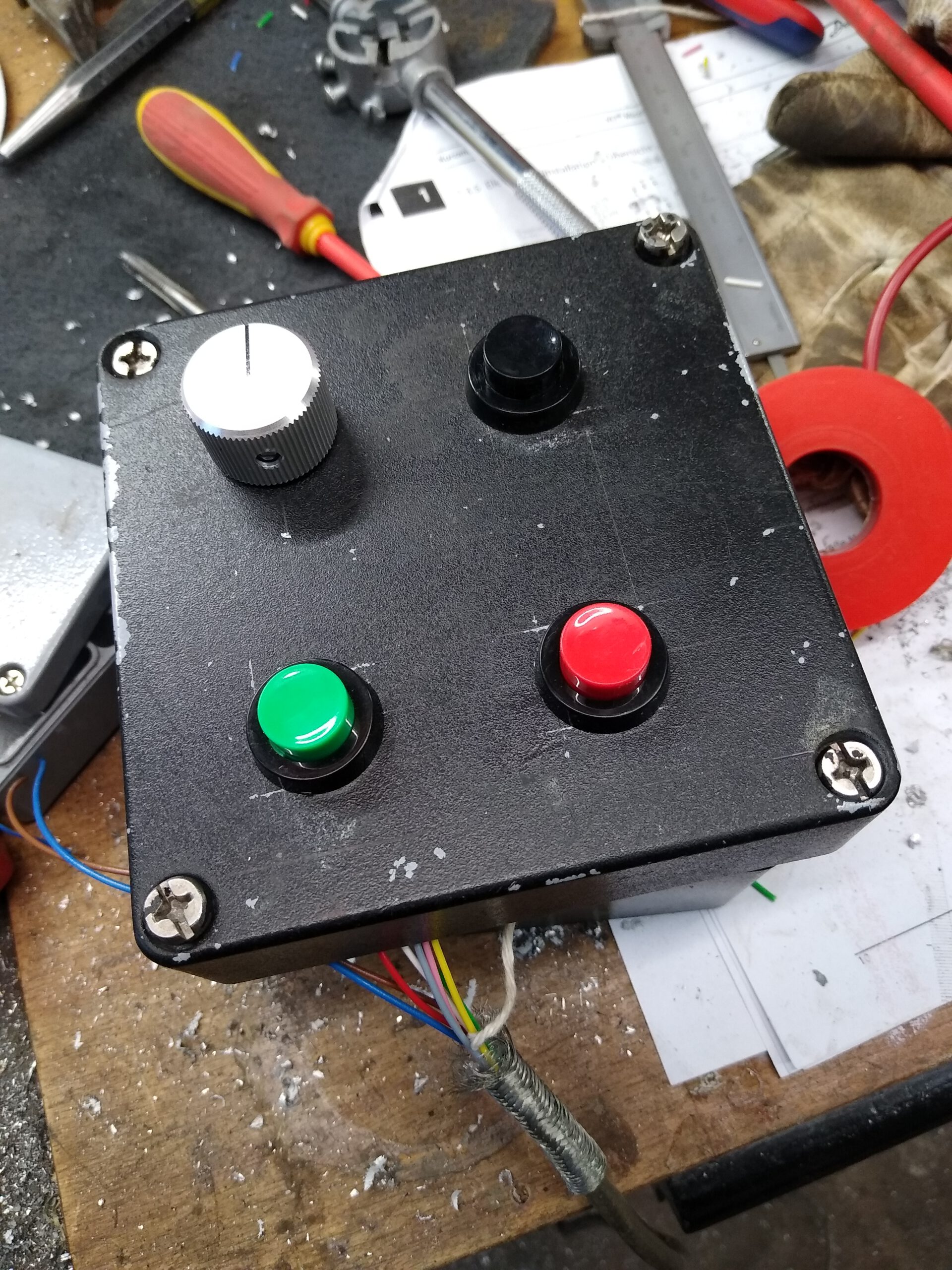
VFD and controls
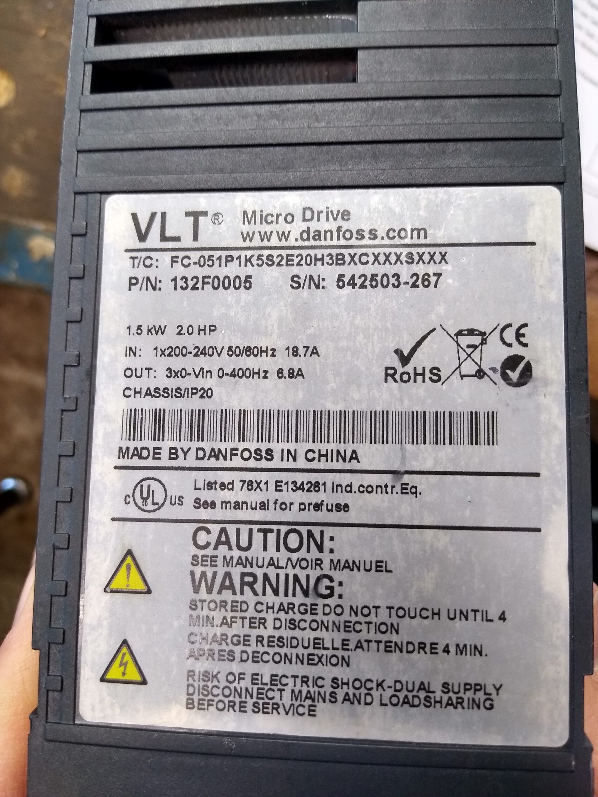
For speed control I use a second hand Danfoss VFD (FC-51) and a self made control box with a potentiometer for speed adjustment and a start and stop button. The third button is not connected yet. When setting up the VFD I was stuck for a while until I finally found out that the stop button must be, of course, a normally closed type.